
Potential dividers
These are used in particular with LDRs and Thermistors to allow only a certain amount of p.d. to be taken from a circuit.
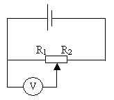
The output voltage can then be calculated using the following equation:
This means that for a large resistance across R1 the output voltage will be greater
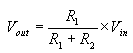
A potential divider circuit can be constructed as follows:
Therefore if the two resistors were of equal size the output voltage would equal half the supply voltage.
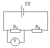
In this circuit either of the two resistors can be replaced with an LDR or thermistor to create a circuit able to detect and provide a measure for environmental changes. Take the following example:
Here R2 has been substituted for a thermistor, therefore if it is in a cold environment, its resistance will increases, so R1 will become smaller when compared to R2 and thus the output voltage will decrease.
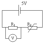
This circuit diagram shows a variable resistor (sometimes refereed to as a potentiometer) which is acting as two separate resistors. The arrow can be freely moved from left to right in order to increase or decrease the relative size of the resistors.
When R1 is small and R2 is large, the output voltage will be small.